Hot stamping foil typically has a total thickness of only 12–30μm and is composed of a PET base film, release layer, color layer, aluminum-coated layer, and adhesive layer. The substrate is thin and the coating is brittle, making it extremely sensitive to tension, tool condition, and static electricity during slitting. There is a saying in the industry: "Thirty percent stamping, seventy percent slitting." A single burr or tension fluctuation during slitting can cause foil breakage, incomplete stamping, or even full-line downtime on high-speed hot stamping machines. This article organizes the causes and countermeasures for five typical problems—burrs, foil breakage, wrinkling, deviation, and uneven winding end faces—according to fault frequency and troubleshooting priority, for reference by on-site operators and maintenance personnel.
1. Burrs, Stringing, and Powder Shedding at Slit Edges
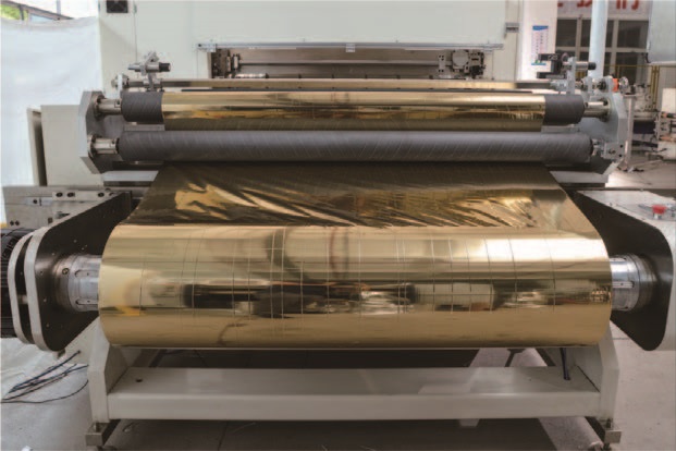
Burrs are the most frequently occurring quality defect in the slitting process, manifested as serrated cuts, string-like burrs, or accompanying aluminum powder debris shedding. During downstream hot stamping, these debris particles form dirty spots and cause missed stamping, directly reducing the yield rate.
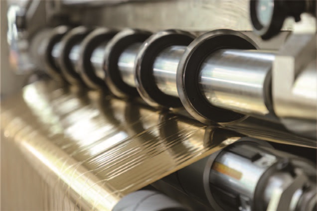
Tool condition is the primary inspection point. After circular or flat blades wear or chip, the cutting edge no longer cleanly cuts the foil by shearing but instead separates the material by tearing, leaving micro-cracks at the edges that are difficult to detect with the naked eye. The judgment method is straightforward: after stopping the machine, lightly touch the blade edge with a finger; if there is noticeable dullness or local chipping, replace or regrind immediately. Blade clearance and overlap are equally critical. For thin hot stamping foil, the blade clearance should be set at 1.2–1.5 times the material thickness, and the upper-lower blade overlap should typically be controlled between 0.05–0.1mm; too small and the foil won't be cut through, too large and the foil surface will be crushed. Blade shaft runout must also not be overlooked; use a dial indicator to measure—radial runout exceeding 0.02mm requires correction.
Tension and static electricity are secondary but non-negligible factors. If unwinding or winding tension is too low, the foil web vibrates in the cutting zone, and the cut naturally becomes uneven; if tension is too high, stretching deformation occurs and burrs worsen. For hot stamping foil, tension is recommended to be controlled at 1.5–3N/mm², with fine-tuning based on foil thickness and supplier data. Regarding static electricity, hot stamping foil uses PET as the substrate, which has good insulation properties; charges generated by high-speed friction will attract foil powder to the cut edges and guide roller surfaces. Static elimination bars or ion air nozzles can be installed before and after the cutting blade, and the equipment grounding resistance should be ensured to be less than 4Ω.
2. Frequent Foil Breakage
Foil breakage is divided into two categories: regular breakage and random breakage. Regular breakage mostly points to tool problems, while random breakage requires sequential inspection of guide rollers, static electricity, and the tension system.
Blade dulling is the most common source of foil breakage. The edge micro-cracks produced by a dull blade "tearing" the foil surface rapidly expand into complete breaks under subsequent tension. If the break position consistently appears at the blade line, prioritize replacing the blade and recalibrating the overlap. If breaks are randomly distributed, inspection should shift to the material path: hard particles embedded in guide roller surfaces, adhesive residue buildup, or bearing seizure can all cause periodic scratching or additional resistance on the foil surface, leading to localized stress concentration and breakage.
Static electricity is an easily overlooked "hidden killer." When static accumulates to a certain level, the foil surface may suddenly adhere to guide rollers or the machine frame, creating a sudden resistance change that instantly breaks the foil. A simple diagnostic method: operate the equipment in a dimly lit environment and observe whether blue-purple sparks appear when the foil leaves the guide roller; or use a static tester to measure the foil surface potential. If static is evident, check whether the static elimination bar has accumulated dust and failed, and whether the high-voltage power supply output is normal.
In the tension system, aging of magnetic powder clutches/brakes is most common. After prolonged use, magnetic powder cakes or is lost, making output torque non-linear. The typical symptom is normal operation at low speed but sudden foil breakage after accelerating to a certain speed. Listening for "rustling" abnormal sounds or jerking during operation basically confirms the need to replace the magnetic powder or the assembly. If the tension sensor is covered with dust or mechanically stuck, the feedback signal becomes distorted, and the controller outputs incorrect commands; regular no-load zero-return checks and static load calibration are also required.
3. Foil Wrinkling
The root cause of wrinkling usually points to tension, but simply lowering tension often yields little effect. What truly needs examination is whether the tension gradient is matched, whether guide rollers are parallel, and whether pressure roller pressure is uniform.
Guide rollers and the material path are the primary suspects for fixed-position wrinkles. If wrinkles consistently appear at the same location, prioritize checking the parallelism and surface condition of the guide rollers in that section. Non-parallel guide rollers, surface scratches or adhesive buildup, and bearing seizure all cause uneven force during foil travel, producing fixed diagonal wrinkles or transverse creases. Checking each guide roller's parallelism (tolerance ≤0.2mm/m), cleaning roller surface contaminants, and promptly replacing seized bearings are the basic steps to eliminate fixed wrinkles.
Random wrinkles require returning to tension and pressure rollers. If unwinding tension is too high, the foil is already stretched before entering the cutting zone and rebounds to wrinkle after exiting the blade; if winding tension is too low, interlayer air cannot escape, and wrinkles are pressed permanently into the roll. For thin anodized aluminum, unwinding tension should be on the lower side, with segmented independent control—unwinding, slitting, and winding tensions adjusted separately. Winding pressure roller pressure is equally critical: insufficient pressure allows air retention, while excessive pressure creates transverse crease marks. For thin materials such as hot stamping foil, the pressure roller linear pressure can start at 0.3–0.5kgf/cm for trial adjustment; for wide-width slitting, segmented pressure rollers are recommended so that pressure in each narrow roll area can be independently adjusted.
4. Deviation and Uneven Winding End Faces
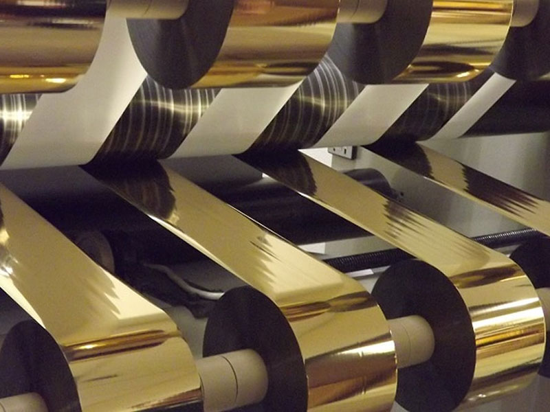
Deviation manifests as lateral wandering of the foil web during travel, with the winding end face appearing as a "tower" or "bell mouth." This problem often has a reciprocal causal relationship with burrs: debris from burrs accumulating on guide rollers or deviation correction sensors causes deviation, while deviation causes the foil web to enter the blade at an angle, worsening burrs. Therefore, troubleshooting should follow the cyclic path of "clean the entire machine → inspect tools → calibrate alignment → optimize tension → verify deviation correction."
Deviation correction system failure is the most common direct cause. Photoelectric or ultrasonic sensors blocked by dust or foil debris cause the correction system to "lose sight." Probe lenses should be regularly cleaned, probe position adjusted to the 1/2 point of the foil web edge, and a ±1mm dead zone set to avoid frequent activation. Poor guide roller parallelism and improper unwinding alignment are structural causes: if the master roll center is not aligned with the spindle during loading, or if guide roller axes are not parallel, the foil web continuously receives lateral force components during travel and gradually deviates.
If deviation correction and guide rollers have been ruled out and end face unevenness persists, the problem is likely in winding tension and pressure rollers. The greatest taboo in hot stamping foil slitting is "running the entire process with one tension value." As the winding diameter increases from empty core to full roll, the diameter ratio can reach 5:1; if tension remains constant, oscillation occurs at small diameters and the outer layers become too tight at large diameters. The solution is to enable taper tension control, reducing full-roll tension to 60%–80% of the starting value. Pressure roller parallelism deviation is another underestimated trap: if the pressure roller axis is not parallel to the winding shaft, one end is tight and the other loose, and the film roll shifts slightly with each revolution, quickly forming a tower shape. During static inspection, use a feeler gauge to measure the gap between both ends of the pressure roller and the winding shaft; the error should be controlled within 0.05mm/m.
5. Daily Maintenance Key Points
Most slitting faults are not sudden but the cumulative result of progressive deterioration such as tool wear, roller surface contamination, and magnetic powder aging. Incorporating the following three items into daily inspection can significantly reduce unplanned downtime frequency:
Tools and blade shafts: After each shift shutdown, touch-check the blade edge for dullness; weekly, use a dial indicator to verify blade shaft runout. Guide rollers and static electricity: Daily, wipe each guide roller surface with a white cloth and check for roughness or sticky areas; clean static elimination bar dust weekly. Tension components: Monthly, auscultate magnetic powder clutch operation sounds; quarterly, verify tension sensor no-load zero-return and loading linearity. For magnetic powder brakes used for over one year, the set current can be increased by 10%–15% to compensate for natural degradation of magnetic powder performance.
The key to slitting fault troubleshooting lies in order. First check whether the blade edge has chipping, then check whether guide rollers and the material path are clean and smooth, then verify tension gradient and static elimination status, and finally recheck deviation correction and winding pressure roller alignment accuracy. This sequence covers the main fault sources from tools to tension and from mechanical to static electricity, helping on-site personnel locate problems in the shortest time and reducing work hours and materials wasted on blind parameter adjustment.
 English
 Deutsch
 Français
 Español
 Português
 日本語
 русский
 한국어
 عربي
 ภาษาไทย
 Tiếng Việt
 Italiano

 Cold Foil Slitter
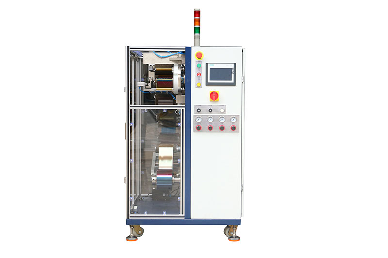 Card Print Ribbon Rewinder
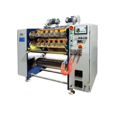 Card Print Ribbon Slitter
 Holographic Foil Slitter
 Digital Enhancement Foil Slitter
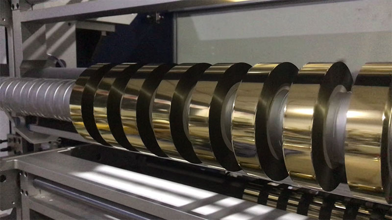
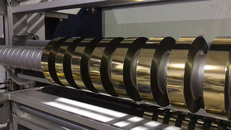
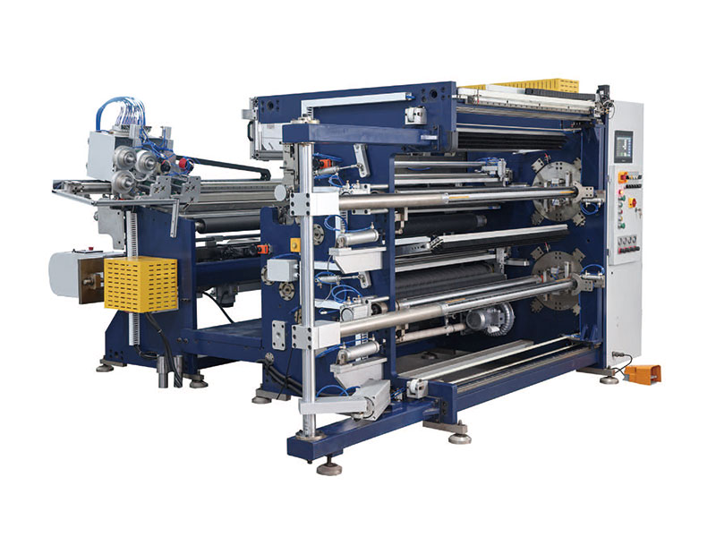 Hot Stamping Foil Slitter RSDS7H 1350 PLUS
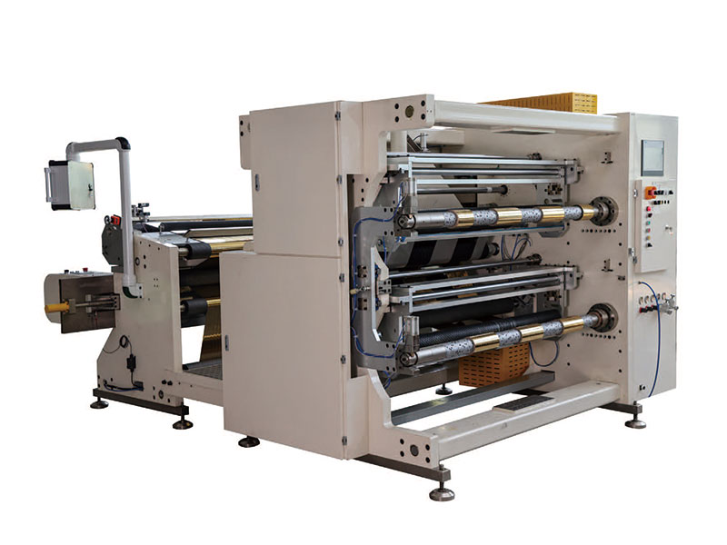 Hot Stamping Foil Slitter (RSDS7H) 1350