Winding deviation and burrs are the two most persistent quality issues in hot stamping foil slitting. They rarely appear alone—a burr left by a worn blade can accumulate on a guide roller and push the web off track, while a deviated strip entering the cutter at an angle puts uneven load on the blade and generates fresh burrs. Treating them as separate problems often leads to temporary fixes that fail within hours.
This guide walks through the root causes and field-tested corrections for both issues, following the same inspection sequence experienced operators use: mechanical alignment first, tension stability second, and electrical correction last.
Why Burrs Form and How to Stop Them
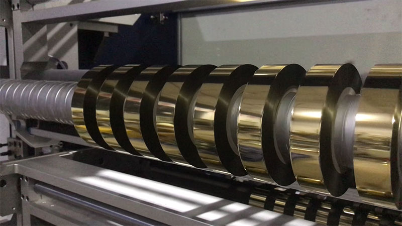
Burrs on hot stamping foil appear as filamentous fuzz, a sawtooth pattern, or visible debris shedding along the slit edge. Because hot stamping foil is typically 6–20μm thick with a PET substrate, even a microscopic blade defect produces a disproportionately visible defect.
Start with the blade, not the settings. Dull or chipped blades are the most common culprit. A worn edge no longer shears cleanly; it tears the foil, creating micro-cracks that expand into burrs or full breaks during subsequent handling. Inspect both upper and lower blades for chipping under adequate light.
The blade overlap and lateral clearance must match the foil thickness. For hot stamping foil, the vertical overlap between upper and lower blades typically falls between 0.5 and 1.5mm, with thinner materials using the lower end of that range. Lateral clearance should be 0.03–0.08mm—roughly the thickness of one sheet of A4 paper. For foil under 12μm, aim for the tightest tolerance possible: just enough to cut cleanly without squeezing the material.
Blade shaft runout is an equally critical but often overlooked factor. Use a dial indicator to measure radial runout at the blade edge. If it exceeds 0.02mm, the shaft needs calibration or the bearing needs inspection. A shaft that runs true but carries a chipped blade will still produce burrs; both conditions must be eliminated.
Static electricity amplifies every other cause. Hot stamping foil’s plastic film substrate generates static rapidly during high-speed slitting. This static attracts foil dust and debris directly to the freshly cut edge, where it embeds and forms what appears to be a burr. Install static elimination bars or ionizing air nozzles immediately before and after the cutter, and verify that machine grounding resistance is below 4Ω. Without static control, even a perfectly sharpened blade will produce edges that look rough.
Roller condition matters more than most operators expect. Foreign objects, dried adhesive, or surface damage on any guide roller creates localized pressure variations that disturb the web as it enters the cutting zone. Wipe rollers with a clean, lint-free cloth daily, and replace rubber pressure rollers that show hardening or flat spots.
Diagnosing Winding Deviation Before It Becomes Scrap
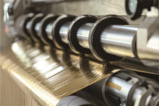
Winding deviation—often called “tower winding” or “telescoping” when severe—manifests as end faces that are not flat, with individual strips shifted axially relative to one another. On hot stamping foil, where the material has almost no bending stiffness, even a minor tension fluctuation translates into visible misalignment.
Check the correction system’s “eyes” first. Photoelectric or ultrasonic sensors that track the web edge are vulnerable to contamination. Foil dust and airborne adhesive particles coat the sensor lens, causing the correction system to lose the edge reference. Clean sensor lenses regularly, position the sensor at the halfway point of the foil edge, and set a dead band of approximately ±1mm to prevent the correction roller from oscillating constantly.
Verify guide roller parallelism. If one guide roller sits even slightly out of parallel with the winding shaft axis, the foil experiences a continuous axial force and “crawls” toward one side. Use a laser alignment tool or the string-line method to check parallelism across the web path. The acceptable tolerance is generally ≤0.2mm/m, with high-precision operations targeting ≤0.05mm/m. Also inspect roller surfaces for uneven wear or adhered debris, which creates differential friction and pushes the web toward the higher-friction side.
Tension stability is the hidden root cause. Many operators adjust the correction sensor repeatedly without addressing the tension closed loop, and the deviation returns as soon as line speed changes. Hot stamping foil requires a tension range of roughly 1.5–3N/mm², set according to foil thickness and supplier data. Two failure modes are common:
• Tension too low: The foil strip vibrates or wanders within the cutting zone, producing wavy edges and inconsistent winding.
• Tension too high: The foil stretches elastically, and when tension releases at the winding core, the stretched layers contract unevenly, causing interlayer slippage.
A simple low-speed test reveals tension uniformity: run at 10–20 m/min and manually compare the tightness of each slit strip. If the center strips feel tighter than the edge strips, the leveling roller angle or taper setting needs adjustment.
The unwind stand must be square and secure. An air shaft that leaks pressure or grips unevenly allows the parent roll to shift slightly during unwinding. Check that the air shaft holds pressure—a drop exceeding 0.05MPa within five minutes indicates a leak. The parent roll itself must be centered on the shaft; an off-center roll introduces a lateral oscillation that no downstream correction system can fully eliminate.
The Interaction Between Burrs and Deviation
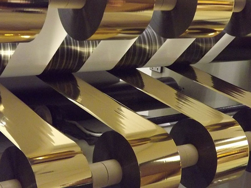
These two faults form a feedback loop that can drive an operator in circles if the connection is not recognized. Burrs shed debris. That debris lands on guide rollers and sensor lenses. Contaminated rollers and sensors cause the web to drift. A drifting web enters the cutter at an angle, concentrating force on one side of the blade. That uneven force accelerates blade wear and produces more burrs.
Breaking this cycle requires a complete inspection sequence rather than isolated adjustments: clean the entire web path, inspect and correct blade condition, verify guide roller alignment, stabilize tension, then validate the correction system. Adjusting only one element in this chain often produces improvement that reverses within a production shift.
A Preventive Rhythm That Works
The operators who achieve consistent slit quality treat maintenance as a scheduled activity, not a reaction to failure.
Daily: Clean blade edges, guide rollers, and sensor lenses. Check for obvious blade chipping. Verify air pressure at 0.5–0.7MPa and drain moisture traps.
Weekly: Wipe all web-path rollers with anhydrous alcohol. Inspect tension system response by running a short acceleration and deceleration cycle. Check blade holder screws and coupling tightness.
Monthly: Calibrate blade shaft runout and roller parallelism. Verify tension sensor zero point. Inspect magnetic powder clutch or brake performance, as these components degrade gradually and produce tension drift that is easy to attribute to other causes.
Quarterly: Replace blades on a schedule based on linear meters cut, not on visible failure. A blade that appears serviceable under casual inspection may already be producing marginal edges that fail downstream.
Keep a log of faults, tension settings, and material batch numbers. Patterns emerge quickly—a particular foil supplier’s thickness variation, a seasonal humidity change that worsens static, or a tension setting that only fails on narrow-width orders.
When to Call for Service
Most burr and deviation issues respond to the mechanical and tension corrections described above. If the problem persists after blade replacement, roller alignment, tension calibration, and static elimination have all been verified, the cause may lie in deeper mechanical issues: worn cutter shaft bearings, a bent guide roller, or a correction actuator with excessive backlash. These require manufacturer service rather than field adjustment.
The most reliable path to consistent quality is to treat the slitting machine as an integrated system. A blade that cuts perfectly on a misaligned machine still produces burrs. A correction system that tracks flawlessly on unstable tension still produces tower winding. Address the fundamentals in order, and the edge quality and winding uniformity follow.
 English
 Deutsch
 Français
 Español
 Português
 日本語
 русский
 한국어
 عربي
 ภาษาไทย
 Tiếng Việt
 Italiano

 Cold Foil Slitter
 Card Print Ribbon Rewinder
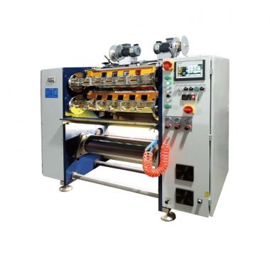 Card Print Ribbon Slitter
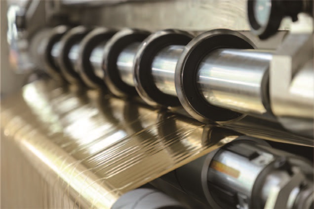 Hot Stamping Foil Slitting Machine
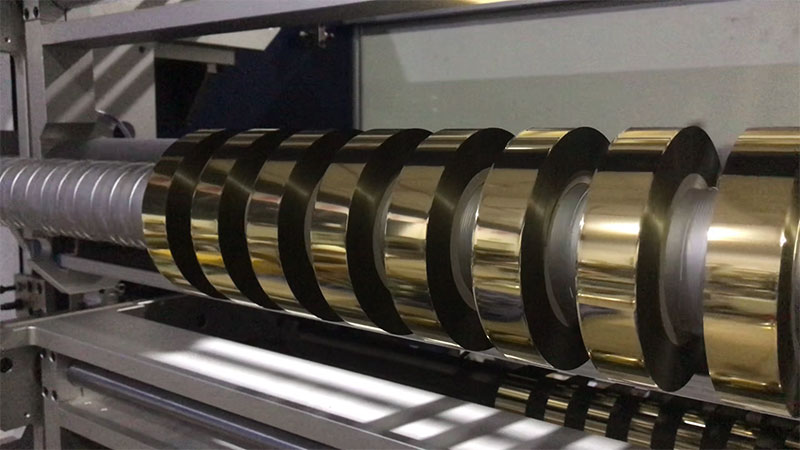 Holographic Foil Slitter
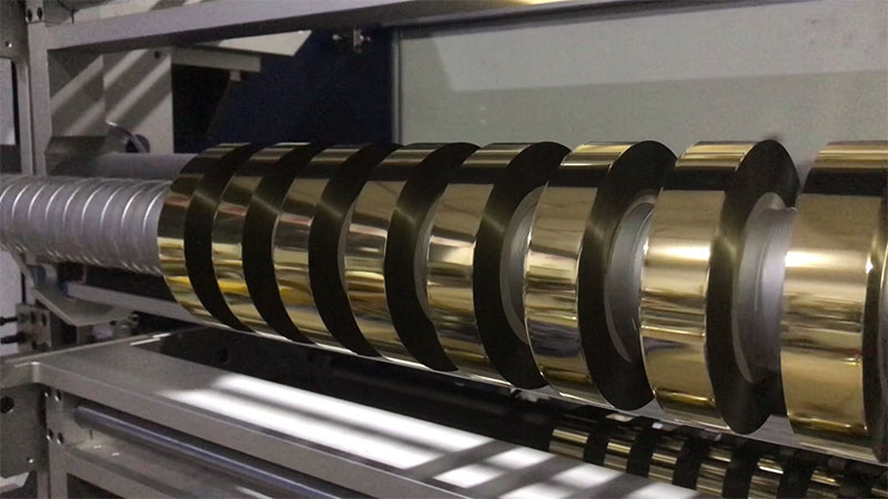 Digital Enhancement Foil Slitter
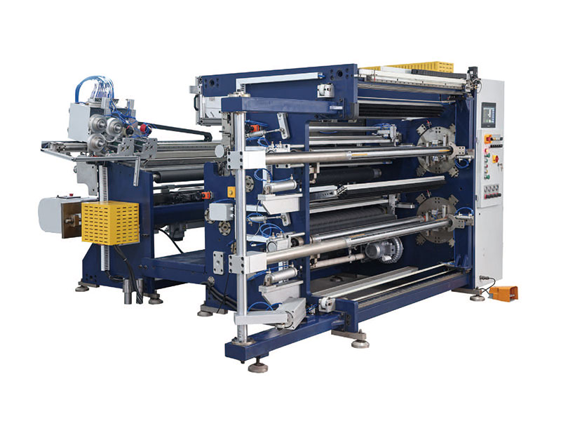 Hot Stamping Foil Slitter RSDS7H 1350 PLUS
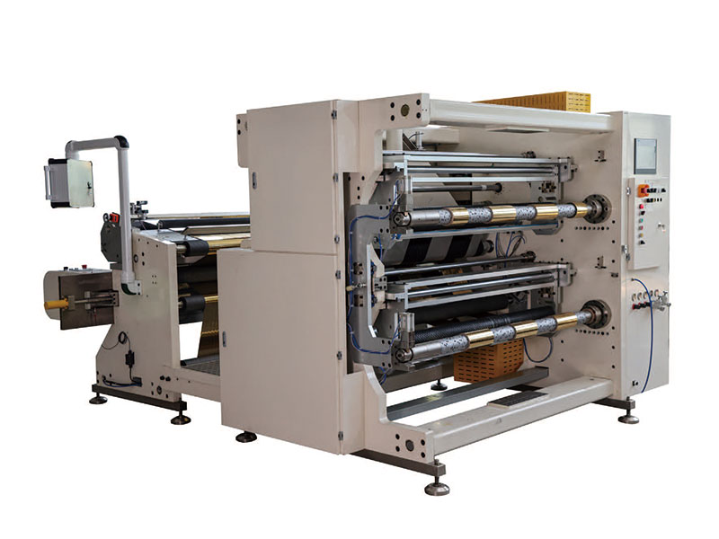 Hot Stamping Foil Slitter (RSDS7H) 1350