Film slitting is a key bridging process in coil processing, and its precision directly determines the yield of downstream products and material utilization. From the optical film on smartphone screens to the separators in power batteries, micron-level width deviations or edge burrs can be magnified in subsequent processes as film breakage, registration errors, or even battery short circuit risks. For a long time, the industry regarded slitting accuracy as a reflection of mechanical assembly level, but with the popularization of high-speed slitting and ultra-thin films, this perception is being corrected: slitting accuracy is not a product of a single step, but rather the result of the dynamic interaction of tension, deviation correction, tool state, and incoming material characteristics. This article attempts to break down the mechanisms of these factors and outline the technical path from empirical control to data closed-loop evolution.
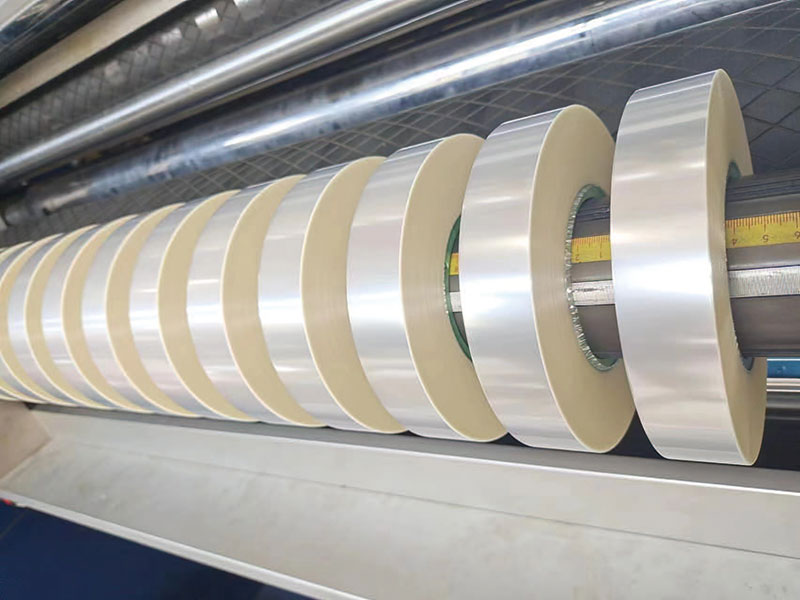
Tension control: the underlying constraint of accuracy
During the slitting process, tension plays a dual role. It not only provides the necessary "necking" support for the tool to keep the cut edge stable at the moment of shearing, but also directly affects the lateral position stability of the film between guide rollers. When tension is insufficient, the film width becomes loose, and even slight airflow disturbances or guide roller runout can trigger serpentine deviation; If the tension is too high, the thin film will undergo tensile deformation, causing the slitting width to rebound after winding, resulting in hidden dimensional deviations. More challengingly, the diameter continuously increases during winding, and maintaining constant tension requires the braking torque to decrease in sync. If this taper control response is delayed, it will cause uneven stress between tight inner layers and loose outer layers, resulting in deterioration of end face uniformity.
Traditional PID tension control is a reactive logic of "adjusting after deviation occurs," with inherent lag under high-speed slitting. The current direction of technological evolution is to build a closed loop using servo drives combined with tension sensors, incorporating the tension ratios of the unwinding and rewinding sections into a unified model, achieving a transition from "passive correction" to "active prediction." For materials sensitive to tension, such as capacitor films and optical films, even if tension fluctuations are controlled within the set value of ±1%, they are enough to affect the microscopic quality of the final slitting end face.
Correction system: The battle between milliseconds and thin film deviation
The lateral deviation of the film during high-speed travel is the primary source of slitting width deviation. Multiple causes of deviation: errors in guide roller parallelism, uneven tightness of the incoming master roll, and even the cumulative effect of thickness tolerances within the film itself, all of which cause the film width to deviate from the set path before entering the blade edge. The task of the correction system is to complete the closed loop of "detection—computation—execution" within milliseconds.
The accuracy of the perception layer directly determines the upper limit of correction. Traditional optoelectronic or ultrasonic edge sensors are easily affected by film transparency, color, and surface reflectance, but the introduction of optical coherence tomography (OCT) edge sensors enables both highly transparent optical films and dark conductive films to achieve submicron edge localization. At the execution level, the response time of servo-electric correction in high-speed scenarios (>100 m/min) has been compressed to within 10 ms. Combined with fuzzy PID and edge position prediction models, advanced correction of progressive offsets caused by material ductility can be applied. It is worth noting that correction and tension are not independent systems: when the correction action changes the lateral position of the film width, the tension distribution on both sides changes accordingly. The ideal synergistic strategy is to fine-tune the pressure of the corresponding tension roller during correction trigger, forming composite correction rather than letting the two systems operate independently.
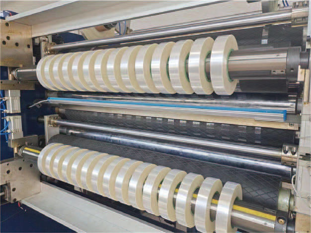
Tools and tool shafts: overlooked sources of micron-level error
The slitting width reference is set by the tool spacing, but the set value does not equal the actual cutting point position. Axial movement of the tool shaft, rotational deviation of the blade, and slight wear on the tool tip during long-term operation all continuously shift the actual cutting line. Research has pointed out that axial displacement of the slitting blade often exists at the start of slitting. If operators rely solely on the finished product width to reverse the tool adjustment, they are prone to repeated corrections and a cycle of constant instability. In high-precision scenarios, using a scale indicator to measure the lateral displacement of the tool shaft during rotation and loading is an effective way to judge the true accuracy of the tool system.
The vibration characteristics of the blade shaft drive are equally noteworthy. The periodic meshing vibrations of gear transmission are transmitted to the tool tip in the form of high-frequency micro-oscillations, leaving barely noticeable "knife vibration patterns" on the ultra-thin film, which poses a hidden risk of breakage in subsequent processes. The linear motor direct-drive tool shaft eliminates this vibration source at its source, reducing the burr height at the edge of the cut edge from an average of 0.12 mm in the previous generation equipment to below 0.03 mm. Additionally, the tool clearance must match the material thickness, usually taking 2%–10% of the material thickness. If the gap is too large, the cut edge will tear and burr growth; if too small, the edge will wear faster.
Incoming material characteristics and process matching: an underestimated variable
Slitting precision cannot be determined solely by the slitting machine. The thickness tolerance of the master roll, the consistency of tightness in winding, and even batch fluctuations in the surface friction coefficient all translate into observable accuracy deviations during slitting. If the incoming film width has uneven longitudinal thickness, its elongation under constant tension will change accordingly, causing periodic fluctuations in the width of the slitted subroll. Similarly, if there are local bulges or depressions on the end face of the mother roll, the lateral position of the film width during unwinding will experience low-frequency oscillation, exceeding the effective compensation range of the correction system.
Matching process parameters is equally crucial. Increasing slitting speed intensifies tension fluctuations and makes correction response more difficult, but lower is not always better—excessively low linear speed actually causes the film to lack sufficient stiffness support during shearing at the cutting edge. For different materials, reasonable velocity windows and tension settings must be determined through process testing, rather than using the same set of parameters. Experienced factories link the thickness curve of the master roll with the tension model of the slitting machine, pre-compensating for known thickness fluctuations during the unwinding stage, and shifting quality control from the slitting process upstream.
From single-machine accuracy to system accuracy
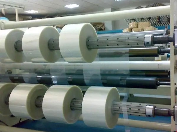
The interplay of these factors explains why simply improving the machining accuracy of a single component often fails to achieve proportional improvements in slitting accuracy. A cutter machine with shaft runout controlled at the micron level, if the tension system responds slowly, the trimming quality remains unstable; No matter how high the correction sensor resolution is, if the distribution of tension in the incoming main coil is inherently disordered, deviation will still occur repeatedly.
The current leading equipment's technical roadmap points to an integrated closed-loop architecture of "perception—decision-execution": distributed sensors collect tension, vibration, edge position, and tool status in real time; machine learning models predict parameter drift trends based on historical data; servo actuators fine-tune within milliseconds. Data from a photovoltaic backsheet membrane manufacturer shows that after introducing this architecture, the loss rate dropped from 1.8% to below 0.7%, and data retrospective revealed the implicit quality fluctuation pattern of the incoming main roll. The significance of this case is that the upper limit of slitting accuracy is shifting from the physical limit of mechanical precision to the algorithmic limit of data closed-loop.
For film processing enterprises, analyzing the factors affecting slitting accuracy ultimately comes down to operable control points. The response bandwidth of the tension system, the environmental adaptability of the correction sensor, the vibration spectrum driven by the blade shaft, and the thickness and tightness distribution of the incoming main roll form the four key points for precision control. Any shortcoming at any point can be magnified into visible width deviations or edge defects during high-speed operation. Incorporating these pivots into a unified parameter management system and using data rather than experience to drive commissioning decisions may be the only way to move slitting accuracy from "qualified" to "controllable."
 English
 Deutsch
 Français
 Español
 Português
 日本語
 русский
 한국어
 عربي
 ภาษาไทย
 Tiếng Việt
 Italiano

 Film Slitting Machine
 Ribbon Slitting Machine
 Tape Slitter
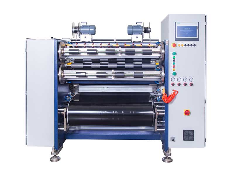 Barcode Ribbon Slitting Machine
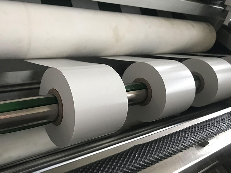 Single Side Adhesive Slitter
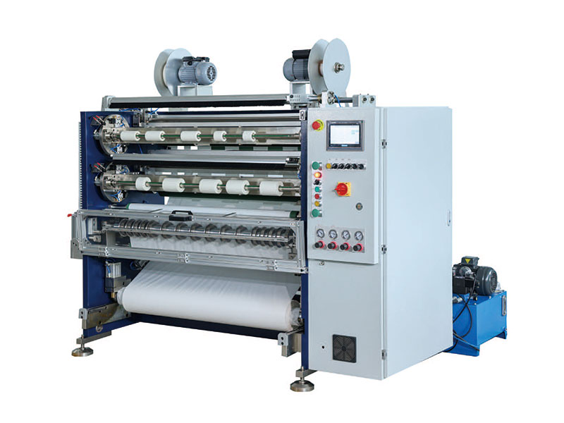 Double Side Adhesive Slitter
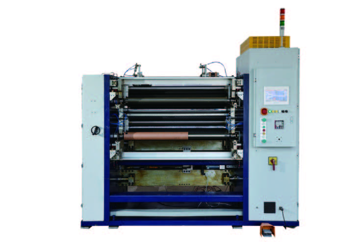 Capacity Film Slitter
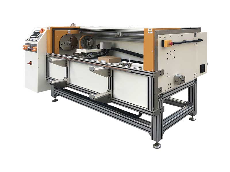 Automatic Foil Roll Cutter