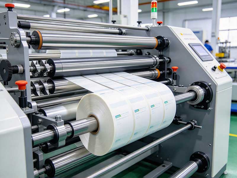
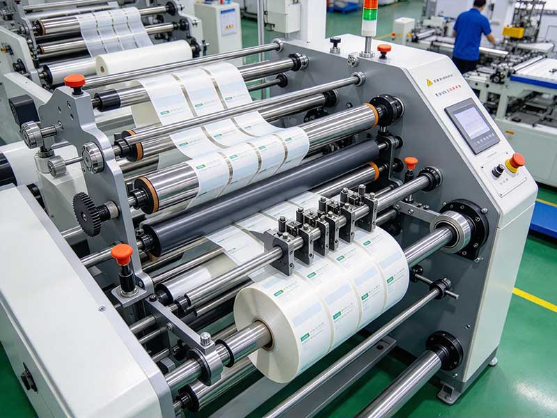
The tension control of self-adhesive label slitting machines is far more complex than that of ordinary paper slitting. The reason lies in the material itself—a 'sandwich' structure composed of three layers of composite material—the surface material, adhesive, and backing paper—which greatly increases its sensitivity to tension. If the tension is slightly high, the backing paper can stretch or even break, causing deformation of the surface material and resulting in inaccurate registration; If the tension is slightly low, the winding is loose, the ends seep glue, and the finished roll will deviate like a snake on the printing press. A qualified tension control system essentially establishes and maintains stable micro-tension environments that do not interfere with each other at different sections of the paper path.
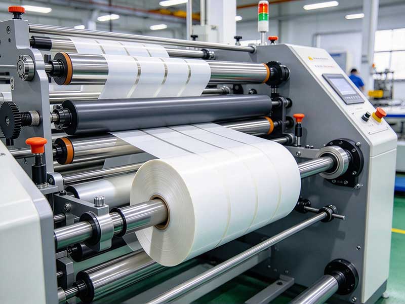
1. Unwinding section: the starting point and partition for tension control
Unrolling is the source of tension along the entire paper path. Large roll self-adhesive may become loose and deformed due to moisture or loss of water during transport or storage before cutting. If directly pulled, the loose edges will instantly transform into tension fluctuations. Therefore, the spinning shaft is usually fixed with an expansion shaft and paired with an automatic deflection correction system (EPC). Photoelectric sensors track the material edges to ensure the paper path remains straight before entering the slitting blade, avoiding longitudinal tension deflection caused by lateral displacement.
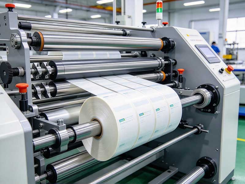
But merely correcting remote areas is far from enough. The core task of the unwinding section is to "isolate" the unstable resistance of the main roll outside the slitting zone. A common practice is to install a rubber roller compression drive between the unwinding and traction sections—a pair of rubber rollers operate at a constant linear speed to clamp the material, using friction to isolate tension fluctuations in the unwinding section from subsequent processes. A more traditional solution uses a dancer roll: the movable roller on the counterweight swing arm is pressed against the paper path by gravity. When the winding resistance changes causing the paper path to loosen or tighten, the swing arm swings accordingly, and the displacement sensor converts this into electrical signals, adjusting the torque of the winding brake or motor in real time to restore the tension in that section to the set value. Both methods share the same goal: to ensure that the material tension entering the slitting blade is not affected by changes in the roll diameter or defects in the coil itself.
2. Slitting and Intermediate Section: The Key Window for Tension Stability
The moment the slitting blade contacts the material is when the tension of the entire paper path is most likely to become unstable. If the tool is not sharp enough, the material will not be "cut" but "torn" off, causing the adhesive to pull strings and stick to the knife at the cut, causing sudden local tension changes and leading to glue seepage and periodic white spots on the end face. Therefore, tension control in the slitting area aims for "low and stable"—the tension is sufficient to straighten the material for precise cutting but must not be large enough to cause additional plastic deformation at the cutting edge.
The tension stability in this section largely depends on the speed matching accuracy between the traction roller and the slitting blade. Traditional mechanical slitting machines link the traction roller and slitting knife roller through gears or synchronous belts, keeping the pulse speed difference between the two within a very small range (for example, a pulse difference on the order of one-thousandth of an elastic limit elongation), thereby maintaining constant tension in the paper path before and after the blade edge. Modern equipment more often uses independent servo drives, where PLCs dynamically coordinate the speed of each roller segment based on linear speed setpoints, resulting in faster response and wider adaptability.
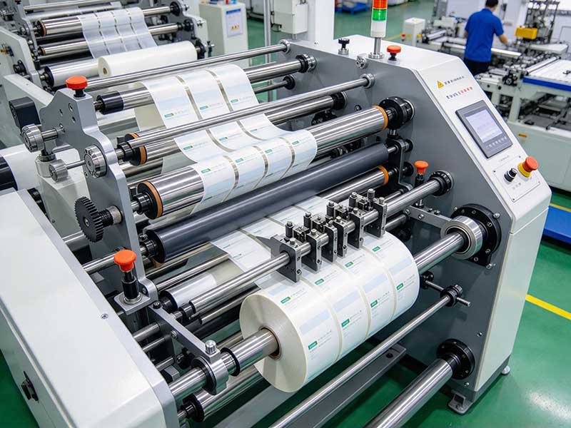
3. Rewinding section: taper tension and slip compensation
Rewinding is the most complex step in tension control because it faces a dynamically changing geometric condition: the coil diameter is continuously increasing. If the winding torque is constant, as the radius increases, the material tension decreases inversely, resulting in a tight core, loose outer layer, and a "daisy core" collapse on the end face.
The classic solution to this problem is taper tension control. The logic is: the winding tension is no longer constant, but gradually decreases according to a preset curve as the coil diameter increases. Initial roll diameter is low, using higher tension to ensure a tight core; As the coil diameter increases, tension gradually decreases according to the taper coefficient, preventing displacement and wrinkles caused by excessive accumulated interlayer pressure in the outer layer. The shape of the taper curve (linear or segmental) depends on material thickness, the softness of the adhesive layer, and the requirements for unwinding subsequent printing, and is usually determined through test papers during equipment commissioning.
However, taper control solves the problem of "whole" tension varying with roll diameter, but it cannot address another unique challenge of self-adhesive slitting: inconsistent tension between slitting strips. When the master roll coating is uneven or there are slight widths differences among the strips after slitting, the required tension for multiple rolls on the same winding shaft will not be the same. If driven rigidly by a solid shaft, some windings will tighten while others loosen. Slip shaft technology was developed precisely for this purpose: each drum is independently fitted onto the slip ring, and when the tension requirement of a particular material changes, the slip amount of the slip ring adjusts accordingly, allowing each reel to maintain the same speed reference while receiving the required torque compensation. This is the key hardware foundation for achieving "independent control of each volume" and eliminating uneven end-face conditions.
4. Scrap Section: The most easily overlooked micro-tension scene
Die cutting waste removal is a frequently overlooked step in the slitting process. Although the diameter of the waste roll is not large, the diameter changes rapidly, and the scrap itself has low strength (only the surface material and adhesive layer, without backing paper support). The tension window is extremely narrow: slightly larger causes breakage, while smaller ones cause poor winding. For this scenario, an effective and low-cost control solution is a magnetic particle clutch paired with a position sensor: the sensor detects the position where the scrap is sagging due to the weight of the pressure roller. When the scrap relaxes and sags to the set position, it triggers the waste collection motor; after tightening, it naturally returns to its position and stops the machine. This intermittent control keeps the tension of the scrap strip at a very low and constant level, avoiding over-tension fracture caused by rapid changes in coil diameter during continuous winding.
5. The central logic of the control system
The actuators in these sections—magnetic powder brakes, servo motors, slip shafts, floating roller cylinders—require a unified control logic for coordination. Modern slitting machines usually use PLC as the main control, with the unwinding section fed back by tension sensors or floating roll position signals, forming closed-loop or semi-closed-loop control; The winding section uses the real-time diameter measured by the encoder, checks tables, or calculates the taper tension set value, then outputs torque commands to the winding motor or magnetic powder clutch via the PID regulator.
A detail often overlooked is the accuracy of the roll diameter calculation. If the curling diameter is inaccurate, the taper curve loses its benchmark. A more advanced approach is to estimate real-time coil diameter by using the ratio of linear speed integration to motor speed, and perform periodic averaging of the results to filter out noise caused by mechanical vibration and single-turn measurement errors. The control algorithm itself is not mysterious; the real difference lies in the actuator's response linearity and mechanical assembly precision—a device with a large multi-reel runout cannot compensate for the periodic tension pulsation caused by even the finest PID parameters.
Conclusion
Ultimately, tension control in self-adhesive label slitting machines is about finding and guarding that extremely narrow boundary between "straightening" and "pulling damage." The partitioning of the unwinding section, the low-stability of the slitting section, the taper and slip compensation of the winding section, and the intermittent micro-tension control of the waste discharge section—each section fulfills its own function and is coupled with each other. The value of understanding this principle lies not in memorizing a formula, but in being able to trace the end face of the finished roll segment by segment along the paper path to determine where tension is out of control or the partition fails. This is what tension control knowledge truly looks like in the workshop.
 English
 Deutsch
 Français
 Español
 Português
 日本語
 русский
 한국어
 عربي
 ภาษาไทย
 Tiếng Việt
 Italiano