Hot stamping foil is one of the most unforgiving materials to slit. At 12–25μm, the multi-layer PET structure—release coat, color layer, aluminum layer, and adhesive—can be permanently damaged by tension fluctuations that would be negligible on thicker films. A machine that runs flawlessly on 25μm standard foil may produce micro-burrs and aluminum dust on 12μm laser film, and a unit optimized for 1600mm master rolls often fails at 10mm narrow-strip precision.
This guide breaks down the specifications that directly determine yield, edge quality, and downstream stamping performance, organized by the parameters that matter most to converters and foil manufacturers.
Width Capacity: Beyond the Maximum Figure
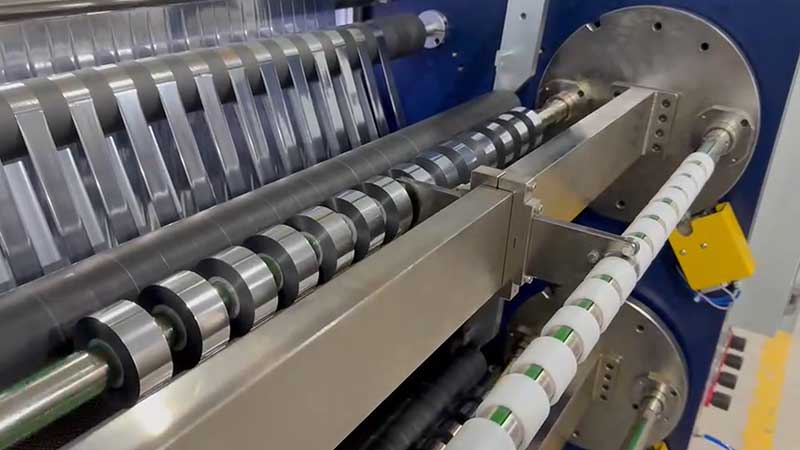
Width specifications have two dimensions that must align with your production reality: maximum unwind width and minimum slit width. Most suppliers advertise the former while understating the difficulty of the latter.
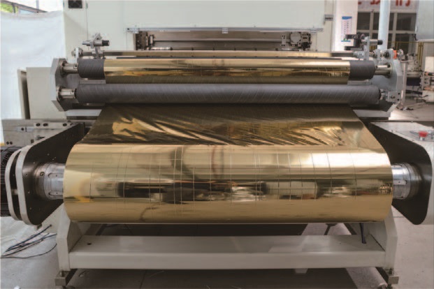
For wide-format operations processing master rolls up to 1600mm, frame rigidity and blade shaft diameter become critical. Wider slitting means greater cantilever forces on the blade shaft; if the shaft flexes even slightly under cutting pressure, the center of the web will not cut through while the edges are over-penetrated. Machines in this class often weigh several tons and require thickened alloy steel wall panels and dynamically balanced, large-diameter blade shafts to maintain stability at speed.
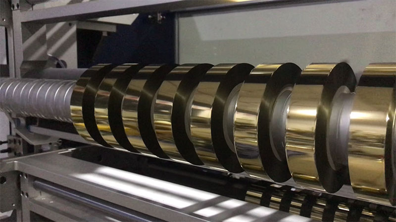
For narrow-strip production below 50mm—common in security threads, decorative bands, and narrow hot stamping lines—priorities shift to tool positioning precision and anti-winding design. Manual locking systems are prone to dimensional drift because uneven clamping forces allow axial movement during operation. Hydraulic locking or high-precision slip shafts are the reliable choice when slit widths are measured in millimeters. If your order profile includes frequent width changes, automatic tool positioning can reduce changeover time from hours to minutes.
A practical benchmark: if your master roll is 640mm and your finished rolls are 2cm wide, the machine must hold ±0.5mm tolerance at that narrow width. Trial cutting with your narrowest material is the only reliable verification.
Tension Control: The Specification That Determines Whether Your Foil Survives
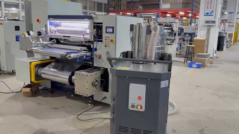
Hot stamping foil’s layered structure is extremely sensitive to mechanical stress. Tension control is not a feature—it is the foundation of whether the machine produces sellable product.
Open-loop versus closed-loop. Open-loop systems relying on preset values and magnetic particle brakes are acceptable for low-speed, non-critical applications below 100 m/min, but they cannot compensate for diameter changes during winding or acceleration/deceleration disturbances. For hot stamping foil, closed-loop servo tension control using tension sensors or floating rollers is the minimum acceptable specification. A quality system maintains tension fluctuation within ±1% to ±3% of the set value; high-end systems achieve ±0.5N precision.
Taper tension is non-negotiable. As the rewinding roll diameter increases, maintaining constant tension causes outer layers to compress inner layers, producing “chrysanthemum core” defects, trapped air, or aluminum layer transfer. Taper tension automatically reduces winding tension according to a preset curve as roll diameter grows. For hot stamping foil, a taper coefficient between 60% and 80% is recommended, with final tension reduced to 40–70% of the initial value. Machines without taper functionality are unsuitable for quality hot stamping foil production, regardless of other specifications.
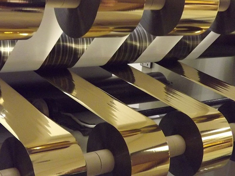
Slip shafts for wide-web, multi-strip production. When a wide web is divided into multiple narrow strips, each strip no longer behaves as part of a continuous web. Differences in strip width, knife penetration, and winding diameter create unequal tension between individual strands. Without independent slip compensation, some strips become tight while others remain loose. A 3-inch slipping friction air shaft for rewinding ensures stable tension across individual rolls.
Slitting Method: Cutting Versus Tearing
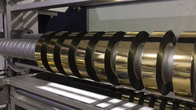
The difference between a clean edge and a burred edge is the difference between cutting and tearing. A dull blade or improper blade geometry presses and fractures the foil rather than shearing it cleanly, producing microscopic burrs and aluminum dust that contaminate the web and cause hot stamping defects.
Circular shear cutting is the industry standard for hot stamping foil. Upper and lower rotary blades produce a smooth, clean cut with minimal deformation. Razor blade or crush-cut systems are less suitable for PET-based foil because they tend to create edge deformation or incomplete separation.
| Blade Parameter | Specification Guidance |
| Material | Tungsten carbide or diamond-coated for PET wear resistance |
| Upper knife angle | 15°–20° for 12–30μm foil to achieve shear rather than squeeze |
| Clearance/overlap | Precision-adjustable, stepless |
| Shaft runout | ≤0.01mm to prevent incomplete cuts in center positions |
For laser foil and holographic materials where any roller contact risks scratching the diffraction pattern, air knife slitting is a high-end non-contact option—expensive but necessary for premium products.
Width tolerance benchmarks. Qualified equipment should hold width error within ±0.1mm; quality-focused operations should target ±0.05mm, with ±0.02mm recommended for laser foil and other special materials. End-face misalignment after winding should stay within ±0.2mm; otherwise, the roll may track poorly on the hot stamping machine and cause registration errors.
Guide Rollers and Mechanical Rigidity: The Silent Quality Factors
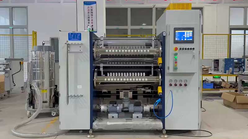
Every roller that contacts the foil surface is a potential source of scratches or micro-vibrations that damage the coating. These mechanical fundamentals determine whether precision is sustained over years of production.
Surface finish. All guide rollers should have a super-mirror finish with surface roughness Ra ≤ 0.05μm. Standard aluminum alloy rollers with HV700 hardness are common, but the finish specification matters more than the material for coating protection.
Dynamic balance. Rollers must undergo dynamic balancing (G2.5 grade or better) to avoid high-frequency micro-vibrations that damage the hot stamping layer at speeds above 200 m/min.
Cutter shaft rigidity. For widths above 1.6 meters, shaft deflection under cutting pressure causes incomplete cuts in the center while edges are over-penetrated. Thickened alloy steel wall panels and large-diameter dynamically balanced blade shafts are essential, not optional.
Edge position control (EPC). Correction accuracy within ±0.5mm prevents the foil from wandering, which would otherwise cause one edge to develop burrs while the opposite edge remains undercut. Ultrasonic edge guiders are preferred over photoelectric sensors for shiny foils that reflect light unpredictably.
Speed: Effective Output, Not Peak Specifications
Mechanical speeds on hot stamping foil slitters typically range from 200 to 500 m/min, with some high-speed models claiming 550 m/min or more. However, the relationship between speed and quality is not linear.
As slitting speed increases, dynamic errors amplify. Lateral deviation can degrade from approximately ±0.10mm at speeds below 100 m/min to ±0.35mm at speeds above 300 m/min. Tension fluctuation similarly increases, potentially causing edge deformation or winding defects. For ultra-thin foils below 12μm, conservative speeds may be necessary to maintain dimensional stability.
Evaluate effective output rather than maximum speed. Consider changeover time, web threading, and waste removal. A machine with automated tool positioning and quick clamping systems can reduce changeover from 15 minutes to as little as 3 minutes, significantly improving real-world productivity even if peak speed is moderate.
Core Specification Summary
| Parameter | Entry-Level | Quality-Focused | High-End |
| Slitting width tolerance | ±0.1mm | ±0.05mm | ±0.02mm |
| Tension control | Closed-loop, ±3% | Closed-loop, ±1% | Servo closed-loop, ±0.5N |
| Taper tension | Optional | Standard, 60–80% | Programmable curve |
| Blade type | Razor or crush | Circular shear | Circular shear, carbide |
| Max mechanical speed | 200 m/min | 400–500 m/min | 500–550 m/min |
| Unwind diameter | 600–800mm | 800–1000mm | 1000mm+ |
| Min slit width | 30mm | 20mm | 10mm or less |
| EPC accuracy | ±1mm | ±0.5mm | ±0.2mm |
Data synthesized from industry specifications.
Matching Specifications to Your Material Mix
The most common procurement mistake is specifying a machine for the widest and fastest requirements while neglecting the narrowest and thinnest. A 1600mm machine rated at 500 m/min may not achieve that speed on 12μm laser foil at 10mm width without exceptional tension control and shaft rigidity.
Before finalizing a purchase, provide your supplier with your actual production profile: the widest and narrowest foils, the thickness range (including any laser or holographic grades), and your target output per shift. Request a trial run using your specific material grades. Inspect cut edges under magnification—the ideal result is a smooth cross-section with no white fluff, fine serrations, or aluminum dust.
For converters running multiple foil types, consider whether a single machine can be configured with interchangeable blade systems (shear for standard foil, air knife for laser) rather than compromising on one method. The additional investment in modularity often pays back faster than a second dedicated machine.
Ready to evaluate a hot stamping foil slitting machine against your production requirements? Contact our technical team with your material specifications and output targets for a configuration recommendation and trial cutting arrangement.
 English
 Deutsch
 Français
 Español
 Português
 日本語
 русский
 한국어
 عربي
 ภาษาไทย
 Tiếng Việt
 Italiano

 Cold Foil Slitter
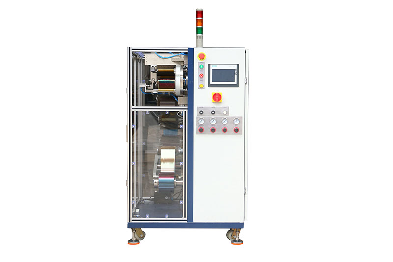 Card Print Ribbon Rewinder
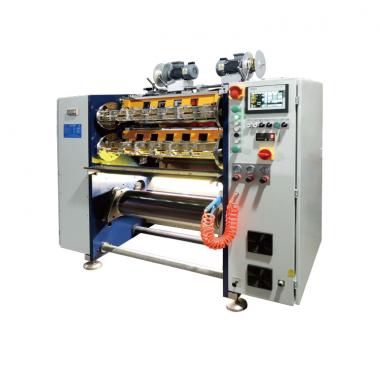 Card Print Ribbon Slitter
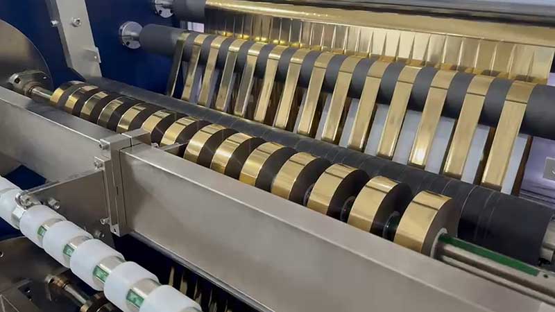
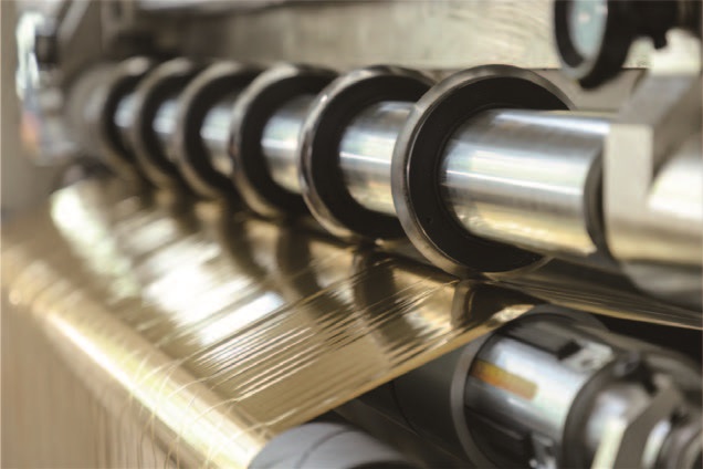 Hot Stamping Foil Slitting Machine
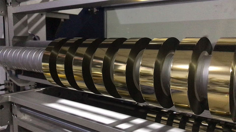 Holographic Foil Slitter
 Digital Enhancement Foil Slitter
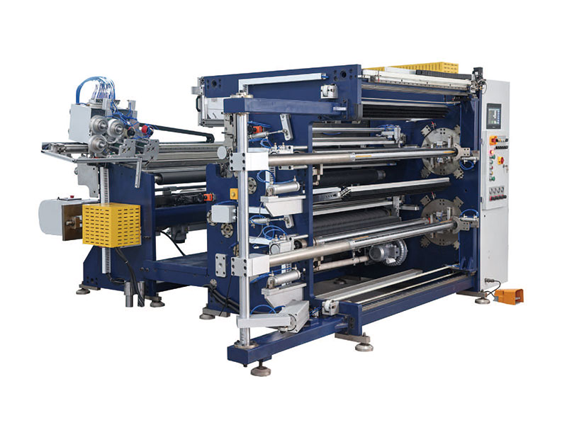 Hot Stamping Foil Slitter RSDS7H 1350 PLUS
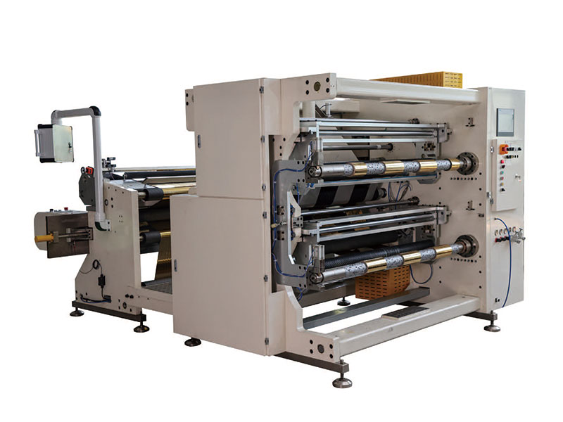 Hot Stamping Foil Slitter (RSDS7H) 1350